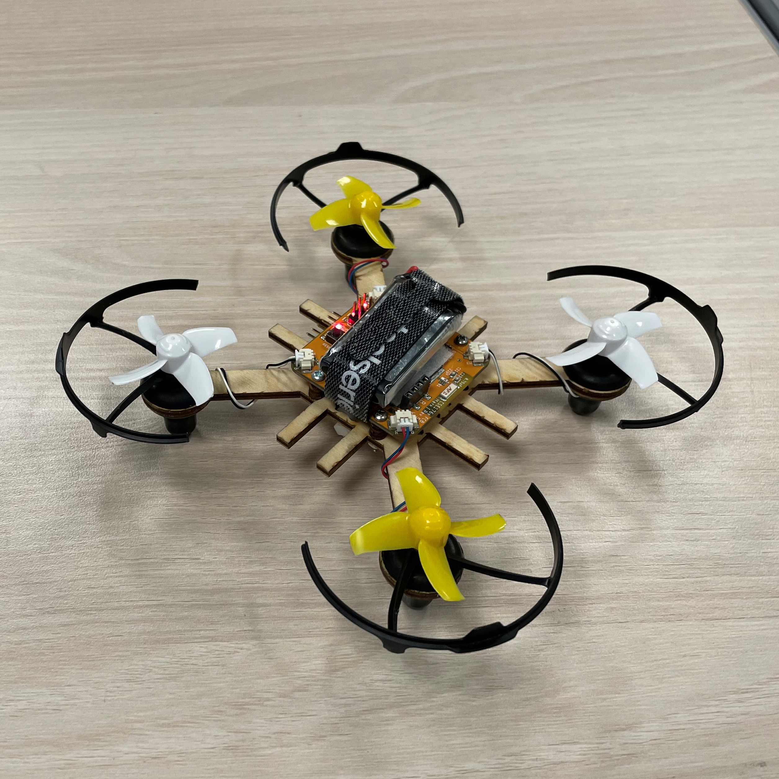
Mini quadcopter
Flight video
Hardware Design
Reference Design for Tuning

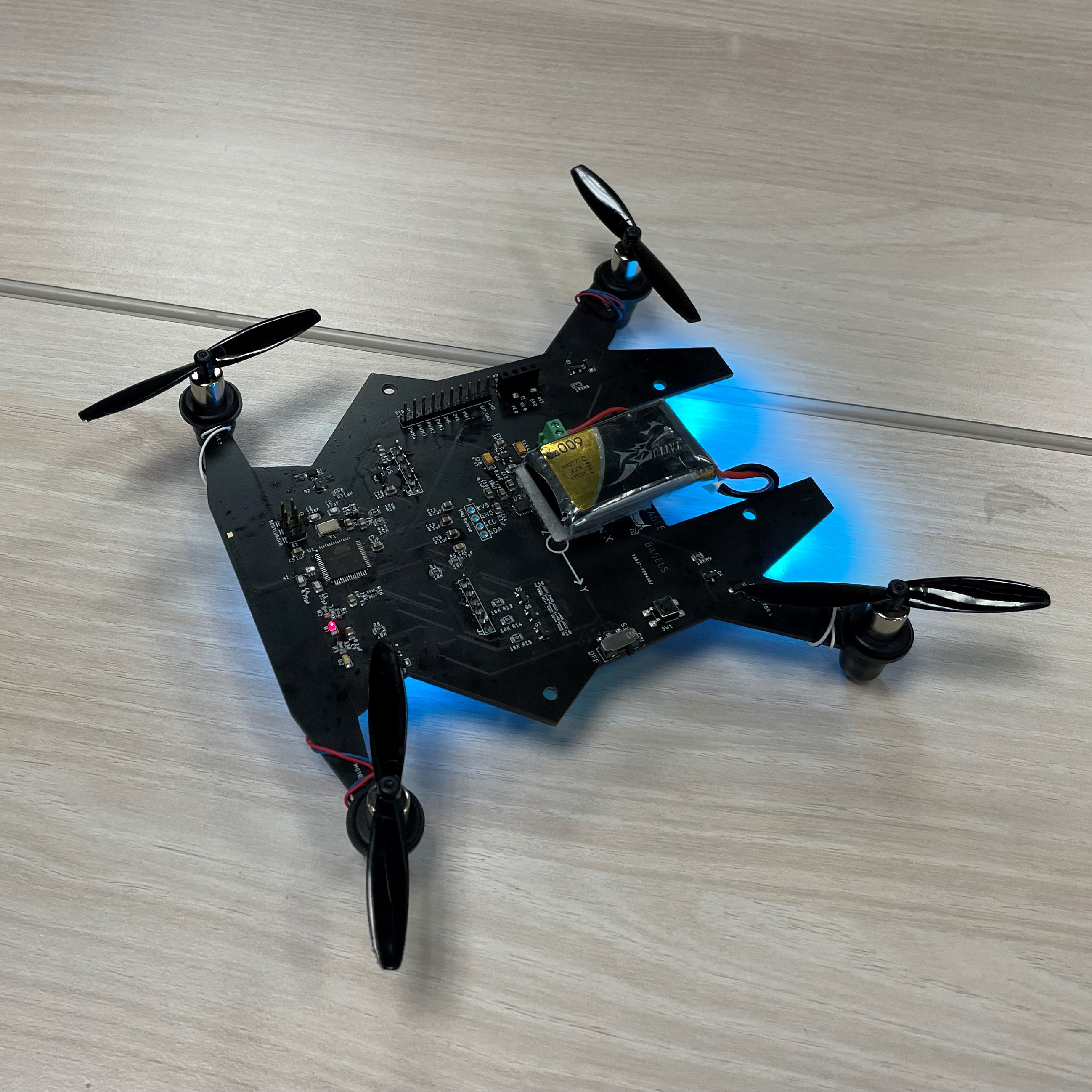
Our design

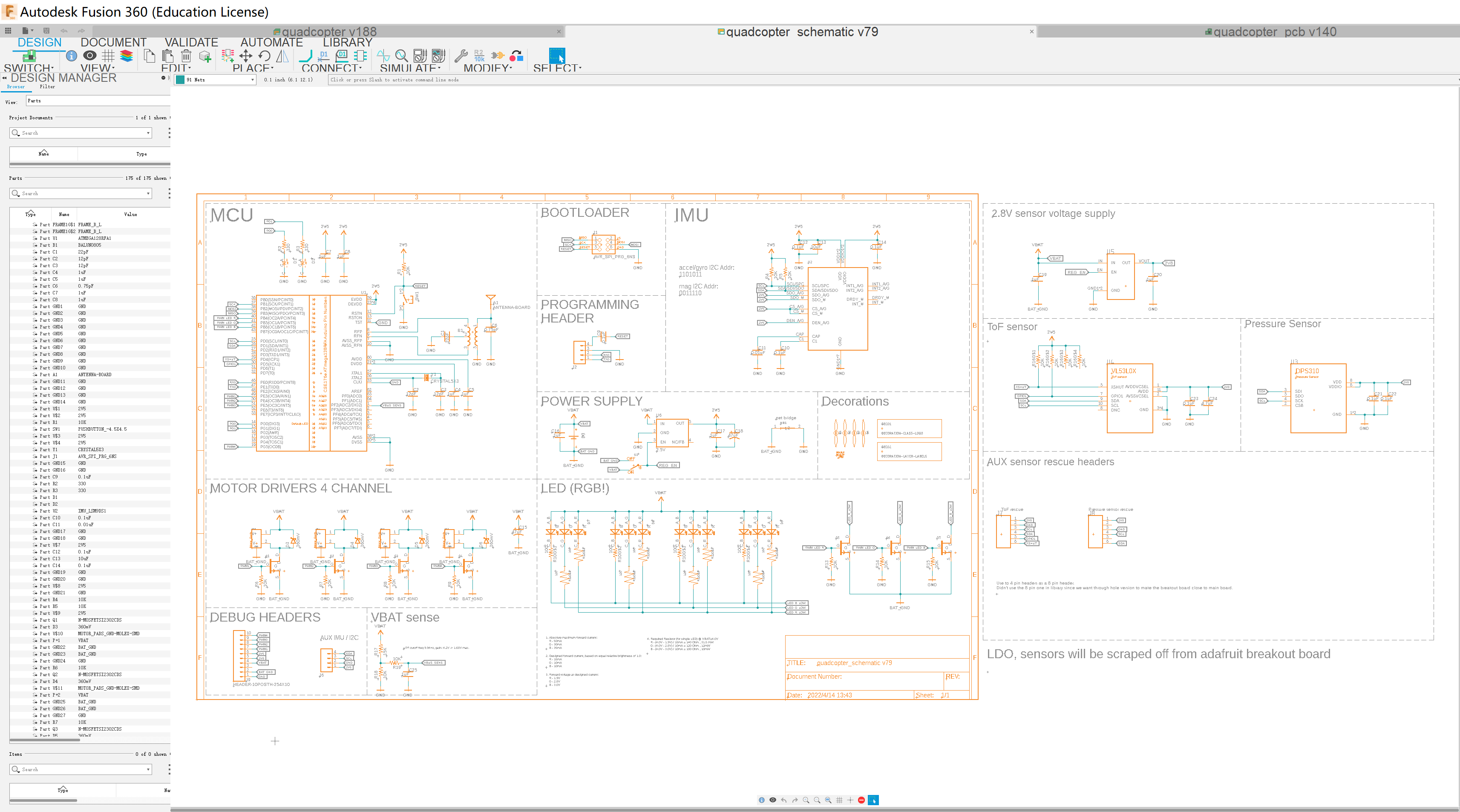
Schematics
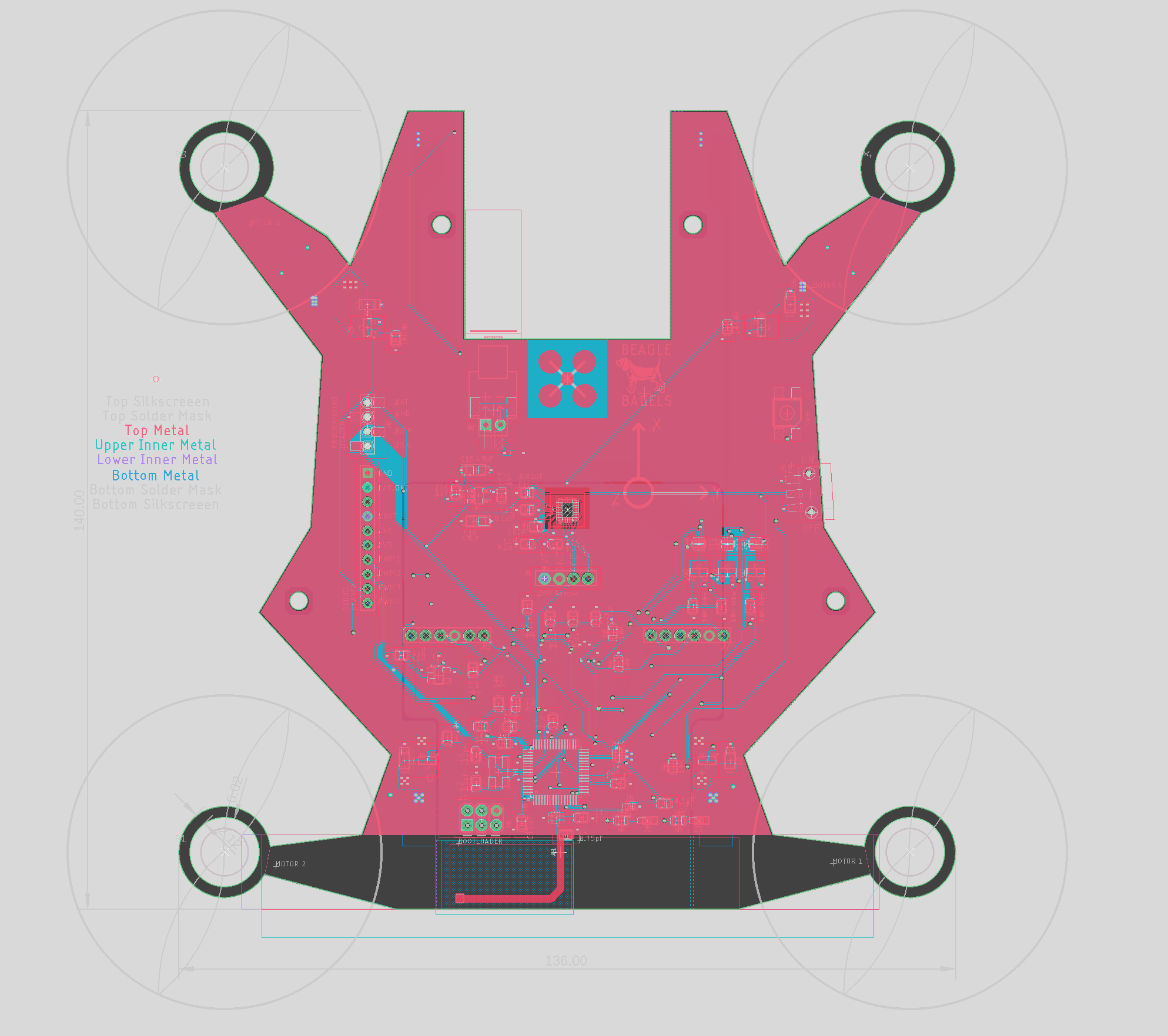
PCB
State Estimation
Attitude
Attitude estimation is achieved fusing gyroscope with accelerometer. We always assume that the quadcoptor is affected ONLY by gravity, therefore the direction of sensed acceleration is the -Z axis of the world.
We used euler-angles to parameterize the orientation, and estimate them in the order of roll - pitch - yaw.
For roll and pitch axis, there are two sources of information.
- direction given by gravity
- last filtered output + dt * angular velocity
They are filtered using a complementary filter as shown:
The two sources of roll is fused first. Then, the filtered result is used to compute pitch along with acceleration data. Finally, it is filtered with gyroscope info on pitch.
Empirically, we found that the complementary gain need to be around 0.99 to achieve good filtering. The key is that the assumption that the sensed acceleration is only gravity is incorrect, especially in early times when the flight controller is unstable.
A large complementary gain will cause error in filtered outputs converge to the “correct” angle from acceleration slowly. During our tuning of the complementary filter, we observed this effect: given the quadcoptor a 90 degrees step input, the filtered output will change and slowly converge to the final output. However, we found that the integrated gyroscope value is not 90 degrees. The scale of the angular velocity need to be multiplied by ~1.05 to obtain the correct value. After this change we found the harm of a large complementary filter is minimized. I encourage this calibration be made a part of the quadcoptor class.
Altitude
Our quadcoptor have a DPS310 pressure sensor on board, which can provide height data relative to the starting point. We coded a kalman filter in MATLAB and used matlab code generation to transfer into C code. We verified the filter using synthetic data:


On the quadcoptor, we project the measured acceleration to the world coordinate using the filtered attitude, and take the Z component as the 1d acceleration measurement.
\[a_z^W = \sin(\theta_p)a_x - \sin(\theta_r)\cos(\theta_p)a_y + \cos(\theta_r)\cos(\theta_p)a_z\]and we use the DPS310 library to convert pressure to height.
Transmit data to Simulink
For faster parameter tuning and data logging, we transmited arrays of float data to simulink. Simulink is not good at fast but small serial prints. Therefore, we buffer our data in arduino and send them as frames.
We used this template to automate the packaging process:
template<typename T, size_t buf_length>
class SimulinkReport{
    public:
    void append(const T& packet){
        if (current_write_idx >= buf_length){
            transmit();
        }

        auto writeAddress = buffer + sizeof(float)  + (current_write_idx) * sizeof(T);
        memcpy(writeAddress, &packet, sizeof(T));
        current_write_idx++;
    }

    bool transmit(){
        // prepare package header and end for simulink to recognize
        memcpy(buffer, "SSSS", 4);
        memcpy(buffer + sizeof(float) + (buf_length) * sizeof(T), "EEEE", 4);

        Serial.write(buffer, 2 * sizeof(float) + buf_length * sizeof(T));
        current_write_idx = 0;
    }

    bool isFull(){
        return current_write_idx >= buf_length;
    }

    uint8_t buffer[2 * sizeof(float) + buf_length * sizeof(T)];
    private:
    size_t current_write_idx = 0;
};
to use which one only need to call append() repeatedly.
On simulink side, we used the serial receive block in Motor Control Blockset. Set the starting data to ‘SSSS’ and ending data to ‘EEEE’. This 4 chars occupy the size of a float, aligning the data. Data size also need to match the buf_length and size of T.
Flight Control
We used PID control on Roll, Pitch, and Yaw angular velocity. We used a approximate model to guide our tuning:
\[G(s) = \frac{1}{s/20 + 1} \frac{50}{s^2}\]In which $\frac{1}{s/20 + 1}$ represent the inertia of the rotor and propeller, which need to have velocity to gain thrust, and $\frac{50}{s^2}$ represent the 2nd order system formed by thrust to angle through inertia. In our control, a input of $+1.0$ indicates $+ 50\%, -50\%$ power on opposite sides.
PID controller
We coded our PID controller with two modifications:
We added low pass filtering to the derivative (as simulink implements its PID block) It is implemented as
which is equivalent to $\frac{Ns}{s+N}$. When $s « N$ it is approximately the derivative. We used $N=250$. Its effect is most evident and helpful in Yaw control.
We implemented the back-calculation anti-windup method according to simulink document. This is to subtract the difference of actual output and uncapped PID output from the I integrator when the PID output is capped by the motor mixer.
Citing simulink documentation, the back-calculation is implemented as:

We found this modification allows larger I gain, and larger I gain helps to stabilize the quadcoptor to nonmodeled disturbances.


